What Must an Aluminium Foil Connector Do in a Duct Run?
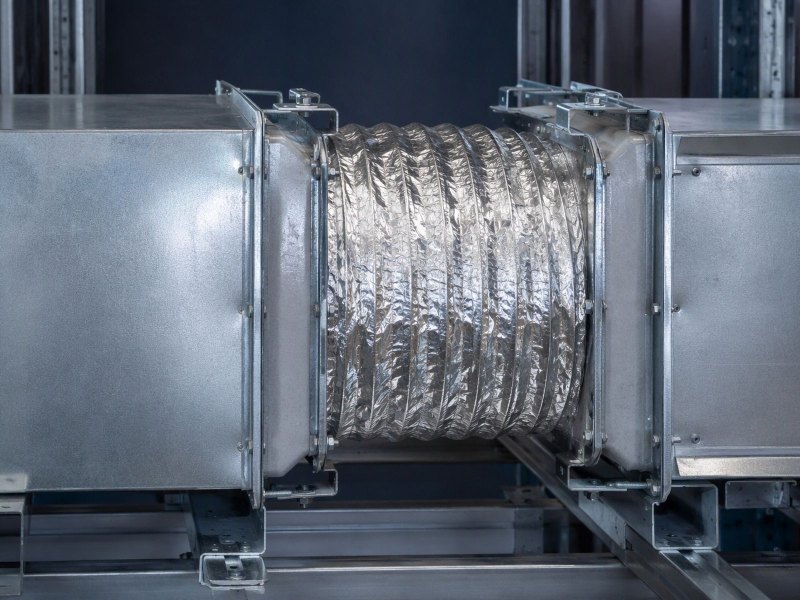
Formed foil absorbs movement and isolates vibration where rigid sheet would pass it along.
What Must an Aluminium Foil Connector Do in a Duct Run?
A connector that cannot move is a bracket. That difference decides whether a duct run stays quiet and tight, or cracks at its first fold.
A duct connector or expansion joint is a short, formed foil section that absorbs movement, isolates vibration, bridges misalignment and allows thermal growth between two rigid parts.
Below, the part is followed from duty to delivery: what it must do, why foil suits it better than sheet, and what an enquiry must contain.
What Is a Duct Connector or Expansion Joint Asked to Do?
Four duties arrive at once, and they pull against each other. A part that satisfies one can fail the next.
It absorbs movement, isolates vibration, bridges misalignment between sections and takes up thermal growth, while still holding the air path and staying tight enough for the run.
Dive deeper
Take a duct run apart at a joint and you find two rigid assemblies that must meet without being locked solid. The short piece between them is asked to do four jobs at once. It absorbs movement, because fans, building sway, settling hangers and changing internal conditions all shift one section against the next. It isolates vibration, so the running hum of a fan does not travel down the duct as noise. It bridges the offset left when field-erected sections do not line up after the hangers are set. And it allows thermal growth, so a run that lengthens under warm air does not push its weight into a wall or a roof curb.
Those duties pull against each other. A part stiff enough to hold its shape resists movement; a part soft enough to move freely can sag or balloon. A formed foil section settles the argument by being thin, short and shaped, so the metal bends where the design intends, not where the load pushes. That is the case for the part, and it explains why the same section appears at a fan outlet and at an equipment connection.
Specifying starts with naming the dominant duty, because a vibration break and a thermal joint load the foil differently. The base metal is usually a soft, ductile grade, for example 1050 aluminium foil in 0.18 mm.
Why Does a Thin Formed Foil Work Where Rigid Sheet Would Not?
Rigid sheet can close an opening, but it also carries load across it. That is the difference that matters.
Thin foil deforms locally, so movement is spent inside the connector instead of being passed into the next section, its hangers and the structure behind them.
Dive deeper
A rigid sheet can close an opening, but it does so by carrying load across it. Whatever the duct does at one end arrives at the other as force: a fan pulse, a settling hanger, metal warming up. The sheet is stiff in bending, so it has no way to spend that energy locally. It passes the energy on, and the next weakest item in the chain takes it: a weld, a hanger rod, a wall sleeve or equipment on isolators chosen for another duty.
Thin foil behaves differently because bending stiffness falls away quickly as gauge drops. A flat strip of foil has almost no ability to resist a bend, so a small force produces a large and controlled shape change. Forming then adds back exactly the stiffness the part needs in the directions that must hold: the profile resists crushing, and the clamped legs resist pull-out. The thin wall and the formed shape do separate jobs, and the part only works when both are present.
There is a second gain: because the foil moves instead of transmitting, the run stays quieter, with vibration spent as small bending cycles in the connector rather than radiated from large flat panels. The Wikipedia entry on aluminium foil describes how the metal is rolled thin and where it is used.
Why Do Corrugation and Fold Pattern Decide Whether the Part Survives?
The pattern is the mechanism. It sets where the metal bends, how far it bends, and how evenly that strain is shared.
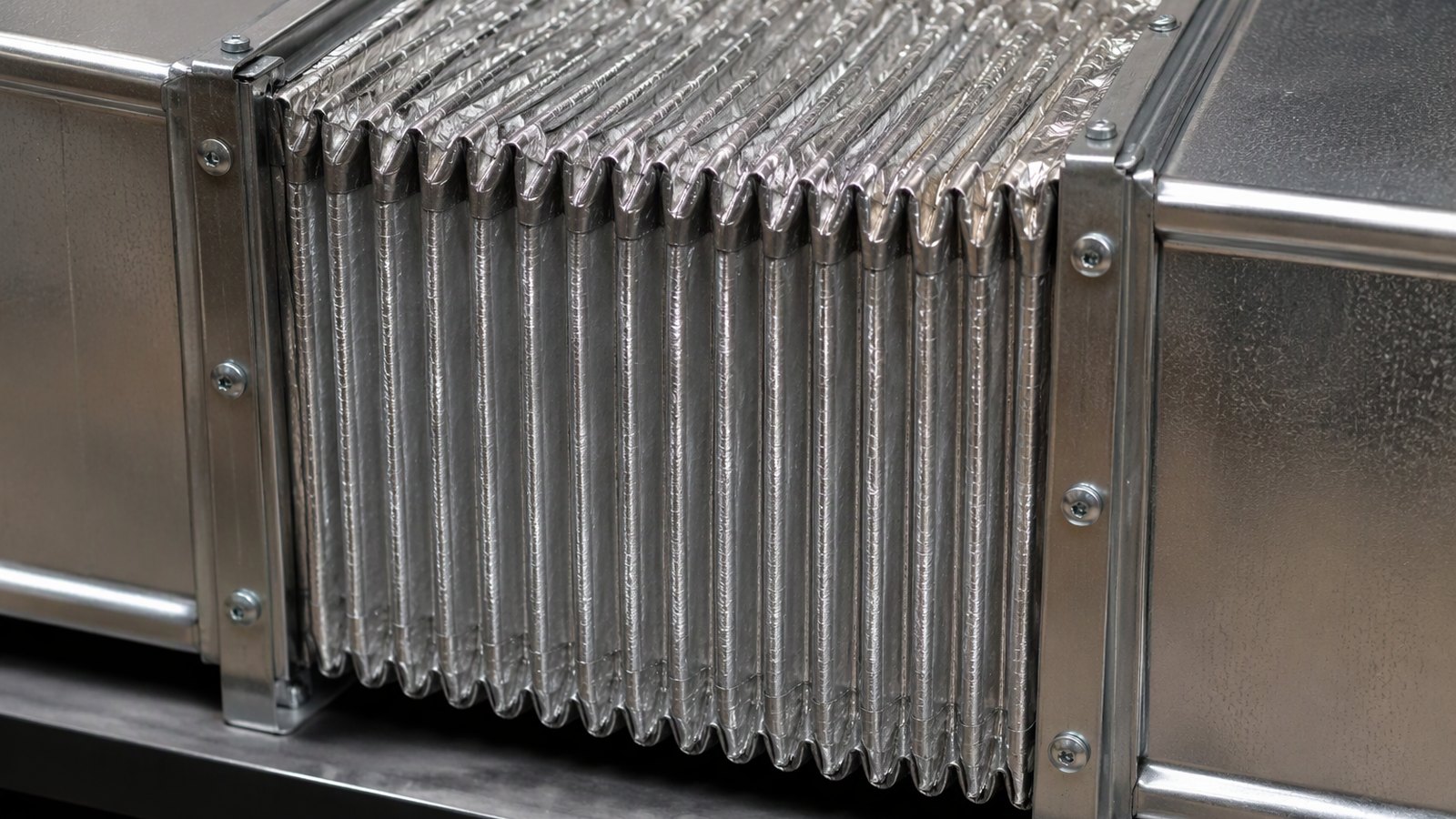
Corrugations turn a flat strip into a row of controlled hinges, so movement is shared across many small bends instead of being loaded onto a single crease.
Dive deeper
A flat strip of foil asked to take repeated movement in one plane will bend along a single line and crack there. Corrugation removes that outcome by turning the strip into a row of shallow ridges and valleys. Each ridge behaves as a hinge that opens and closes a little, so the total movement is shared among many small bends instead of being loaded onto one crease. The profile direction matters for the same reason: corrugations running across the movement act as hinges, while corrugations running along it stiffen the part against the movement it was meant to allow.
The fold pattern does the rest. A connector is usually formed with legs that sit flat under the clamp and a shaped centre that does the moving, and the transition between the two is where the design is won or lost. A generous, gradual transition spreads strain, while a sharp corner collects it. Where a part must accept movement in more than one direction, one set of folds handles extension and another handles the offset, rather than asking a single fold to do both.
Pattern is a tooling decision, so it belongs in the conversation with the forming shop, not in a catalogue number. The foil industry association site covers the rolled product and the way it behaves in use.
How Are Temper and Gauge Chosen for a Part That Must Flex Repeatedly?
Two variables, one trade-off: soft enough to bend again and again, firm enough to hold shape under a clamp.
Soft tempers such as O, H22 and H24 flex furthest before cracking, harder tempers hold a formed shape better, and gauge sets how easily the part bends at all.
Dive deeper
Temper is the first lever. A soft temper such as O, H22 or H24 bends a long way before it cracks and springs back less, which makes it the natural choice for a fold that will open and close in service. A harder temper such as H14, H16 or H18 holds a formed shape more faithfully and resists denting in handling, but it has less room left to bend and cracks sooner at a tight crease.
Gauge is the second lever and trades the same way. Thinner foil flexes under a smaller force, which is what a vibration break wants, but it also dents, tears at a clamp edge and loses shape in handling. Thicker foil survives site abuse and holds a flange face flat, but adds stiffness the movement must overcome. Foil for these parts is supplied from 0.005 mm to 0.20 mm, so the choice is open rather than forced.
The two are chosen together against the duty. A part that cycles many times in service wants the softest temper that still holds its shape, while one fitted once and rarely moved can take a harder temper for durability in transit. A ductile base grade helps, for example 8079 aluminium foil in 0.15 mm, and the forming shop should confirm the temper at which it can hold the fold without surface marking.
What Does the Flange and Clamp Interface Need From the Foil?
The fold gets the attention. The clamped edge is where the part is held, and where a poor fit starts a tear.
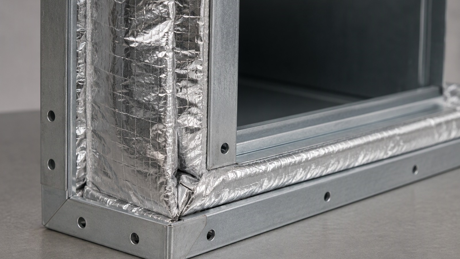
The foil needs a flat land wide enough for the clamp to bear on metal, a clean edge, and an even thickness so band tension is distributed all the way round.
Dive deeper
However elegant the fold, the part is only as good as the line where it is gripped. The clamped edge must sit flat on the flange face, with enough flat land that the clamp or band bears on metal rather than on the start of a corrugation. If the profile begins too close to the edge, the clamp crushes the first ridge and starts a crack where the part is most highly stressed.
The edge itself matters as much. A slit edge carrying a burr or a heavy slitting line gives a notch, and a notch at a clamped edge is the beginning of a tear. A clean, deburred edge cut square to the part lets the clamp load spread evenly, and consistent thickness under a band keeps tension even all the way round.
It helps to be clear about what this interface is not. A gasket seals two faces not meant to move against each other, whereas a connector is a seal expected to move, so the clamp must hold without locking the fold. That is why flat land and the first corrugation are spaced apart, and why the flange face is specified for flatness. The flange area is usually cut from a smooth, formable industrial and technical foil.
Why Does the Part Fail at the Fold Rather Than in the Flat?
Failures cluster in one place, and it is always the same place: the bend that does the work.
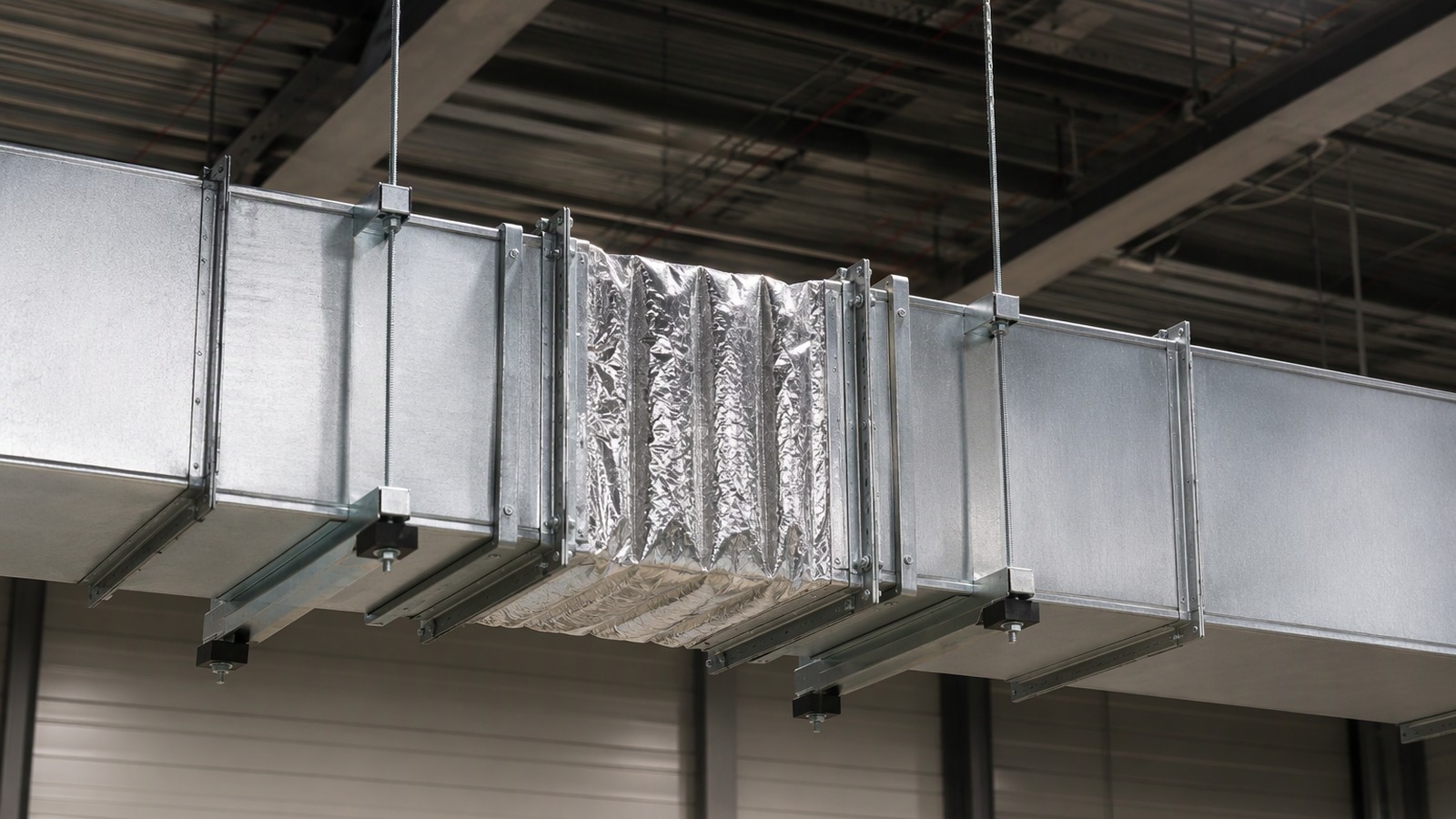
Bending strain concentrates at the fold, so fatigue cracks start there and run along the fold line, while the flat between folds carries load and rarely fails first.
Dive deeper
Look at a failed connector and the crack almost always sits on a fold line rather than in the middle of a flat. The reason is strain concentration. When a strip bends, the outer surface stretches and the inner surface compresses, and the tighter the bend the more of the total movement is absorbed in a very short length of metal. In a flat between folds almost nothing bends, so almost no strain accumulates there.
Repeated cycling then does the rest. Each movement of the duct opens and closes the fold, and the outer fibre of the fold sees a small strain reversal every time. That is the classic route to a fatigue crack: it starts at a surface defect, a tool mark, a tight radius or the edge of a clamp, and it runs along the fold line until the section tears. Handling damage shortens the same path, and so does a fold pre-strained during installation, which starts service with less room to move.
The design response is consistent: soften the temper, open the radius, spread the movement over more folds, and keep clamps and cut edges away from the highest-strain zone. The North American aluminium association site explains how the metal is produced and classified, which is useful background when temper is discussed. The fold geometry itself is settled between buyer and tool designer against the movement the part must take.
How Is the Part Formed, and What Does That Mean for Delivery?
The forming route decides the tooling, the tolerance and the way parts arrive on site.
Coil is slit to width, formed on a dedicated tool, cut to length and packed flat or coiled, so the delivery format follows the tool rather than the other way round.
Dive deeper
A formed connector begins as coil. The coil is slit to the required width, run between rolls or a press tool that produces the corrugation or the fold pattern, then cut to length and, where needed, deburred and inspected. Each step leaves a mark on the delivery format: width is bounded by the slitting line, pattern is fixed by the tool, and length is set at the cut-off.
That has practical consequences for what a buyer orders. A short, deep part arrives as discrete pieces, nested or stacked and banded, and is counted rather than weighed. A long, shallow connector may come as a formed length or as a coil the installer cuts on site, which moves cut-off and edge quality to the installation. Coil for forming comes on 76 mm or 152 mm cores in widths from 100 mm to 1500 mm, so part width and coil width have to be reconciled before the tool is ordered.
It is worth keeping this component in its own category when options are compared. Foil wrapped round a duct for thermal reasons is a covering, whereas a connector is a moving element with a structural duty, bought differently, as specifying foil for duct insulation sets out. The wider picture of how the metal is made and where it goes appears on the European aluminium industry association site.
What Should an Enquiry for a Formed Foil Connector Contain?
A forming shop can only quote what it can picture. A few lines of detail turn a question into a quotation.
Send the duty, the duct size and material, the flange or clamp type, the movement to be accepted, your expected temper and gauge, and the quantity and packing you want.
Dive deeper
An enquiry a forming shop can answer without a meeting carries six things. First the duty: is this a vibration break, a thermal joint, a misalignment bridge, or a combination of them. Second the duct or equipment it joins: size, shape, material and the flange type it will clamp to. Third the movement the part must accept, in words and direction, since a part sized for extension alone behaves badly when the joint must also absorb an offset.
Then the metal: the alloy and temper you expect and the gauge range you can work with, or an open request for a recommendation. Then quantity and the delivery format you need. Finally anything that constrains the shape, an existing clamp, a short flat land, a drawing, or a failed part sent as a reference so the shop can see where it cracked.
Two more details save a round of questions. Say whether parts will be cut or adjusted on site, because that changes edge treatment and packing. And say what the run carries. Minimum order is 3 MT per size, shipped from Qingdao, Tianjin or Shanghai, so grouping sizes in one enquiry simplifies the commercial side. A static joint is a different purchase, as aluminium foil for industrial gaskets and seals explains.
A connector is bought for the movement it must take, not for the shape it arrives in. Name the duty, and the rest follows.