What Does Aluminium Foil Actually Do Inside an Industrial Gasket?
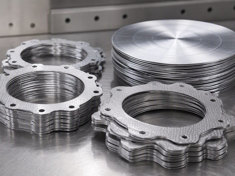
A technical guide for gasket makers, sealing converters, maintenance engineers and foil buyers: what the foil ply does in a layered gasket, which alloy and temper suit a tang, why the cut edge decides, and what an enquiry must state.
A gasket fails at the joint, not in the catalogue. When a layered gasket weeps after thermal cycling, buyers blame the foil before asking what it was doing there.
The foil is a barrier and a compressible metal layer, not the seal. It separates media, spreads load and keeps the facing from being extruded; the elastomer or graphite does the sealing.
This guide follows the part from unwind stand to joint face: what the foil does, why it is layered, which grade suits a tang, what the cut edge decides and what an enquiry must state.
What does the foil actually do inside a gasket?
Inside a gasket the foil is not a seal. It is a barrier and a load-spreading ply, and confusing those roles is where errors start.
It blocks permeation through the joint, holds the facing in place and carries part of the bolt load. Sealing depends on the softer facing conforming.
Dive deeper
Every joint must do three things at once: stop the medium crossing, fill the space between two faces that are never perfectly flat, and stay together while those faces move under load and heat. No single homogeneous sheet does all three well.
A layered gasket splits that work on purpose. The soft facing conforms, wetting out the surface texture of both faces and following each small deviation. The metal ply behind it blocks permeation along the joint and stops the soft material being pushed sideways out of the gap.
So the foil is a separator and a stiffener, never the seal. Where a drawing treats it as the sealing element, the facing is usually missing, or one thin metal layer is asked to close a joint that only a compliant material can close. Aluminium foil - Wikipedia describes the material in general; the duty here belongs to the assembly. Published data on foil grades helps compare alloys and tempers, though the joint still decides.
Read a gasket drawing by asking which layer conforms, which blocks and which carries load. If one layer is expected to do two of those jobs, the part works outside its intent, and the joint shows it after the first few operating cycles. Follow the load path as a second check: where it narrows, stress concentrates, and where it breaks, the barrier breaks too.
Why does foil appear in a layered or spiral-wound construction at all?
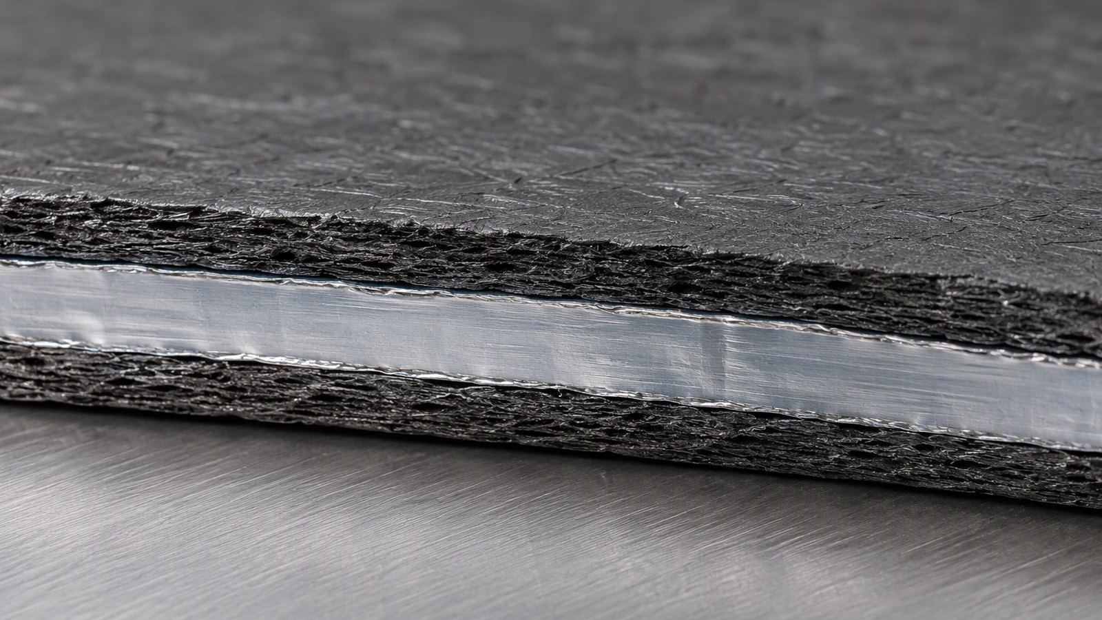
Foil appears in a layered body because a thin metal ply can be wound, corrugated and pressed without machining.
It gives the body a compressible metal skeleton: it springs back after load, spreads seating stress and blocks a straight path through the winding. The soft filler seals.
Dive deeper
A spiral-wound body is built from alternating strips, metal and soft filler, wound together and closed at the ends. The metal strip gives the body something to push against; without it the filler would squeeze out under load and leave a gap no bolt can close.
The same logic applies to a flat layered gasket, where a foil ply sits between two soft facings. The ply gives the stack a defined thickness and a controlled spring, and limits how far the facing is squeezed, so the joint does not close before the soft material has lost its ability to spring back.
A machined ring must be made to a finished size and cannot adapt to two faces that are not parallel. A wound body can. Each ply takes a slightly different share of the load, so a local high point on one face does not lift the ring off the other. That is why foil is in the construction.
The trade is complexity: more plies mean more interfaces, and every interface is a possible leak path if winding tension, filler width or the closing ring is wrong. That is why the industrial and technical foil range is chosen by temper and gauge, and why aluminium foil for heat exchanger fin stock, where the duty is heat transfer, is a different part entirely.
Which alloy and temper suit a gasket tang, and why does a manganese-bearing grade behave differently?
A tang is punched, folded and pressed, so it needs a grade that bends without cracking and holds a spring.
Commercially pure 1050 and 1100 form easily. Manganese-bearing 3003 work-hardens gradually, so it resists fatigue at a folded tang.
Dive deeper
The tang is the small folded or punched tab that locates a gasket, holds a ring in a groove or bridges a joint. It is the most heavily formed feature and usually where a crack starts. A grade that forms cleanly but hardens quickly will crack on a second fold.
Commercially pure grades such as 1050, 1060 and 1100 are soft, ductile and very formable. They suit a tang formed once and then left alone, and a soft metal surface pressed against a facing. They conduct and reflect well, but a thin tang in a pure grade can deform under a load it was never meant to carry.
3003 carries manganese; 3004 adds magnesium as well. The manganese changes how the metal behaves when worked: strength rises with deformation, gradually rather than abruptly. A tang therefore keeps a useful spring after forming, tolerates a second bend and resists the small repeated movements that appear when a joint heats and cools.
Temper follows that logic. Annealed O is the most formable and least springy, while H14, H16, H18, H22 and H24 progressively raise strength and lower elongation. A tang that must hold itself in a groove is usually quarter-hard or half-hard. The two grades published for this work, 3003 aluminium foil, 0.04 mm and 1050 aluminium foil, cover both intentions.
Why does the cut edge matter more here than the face?
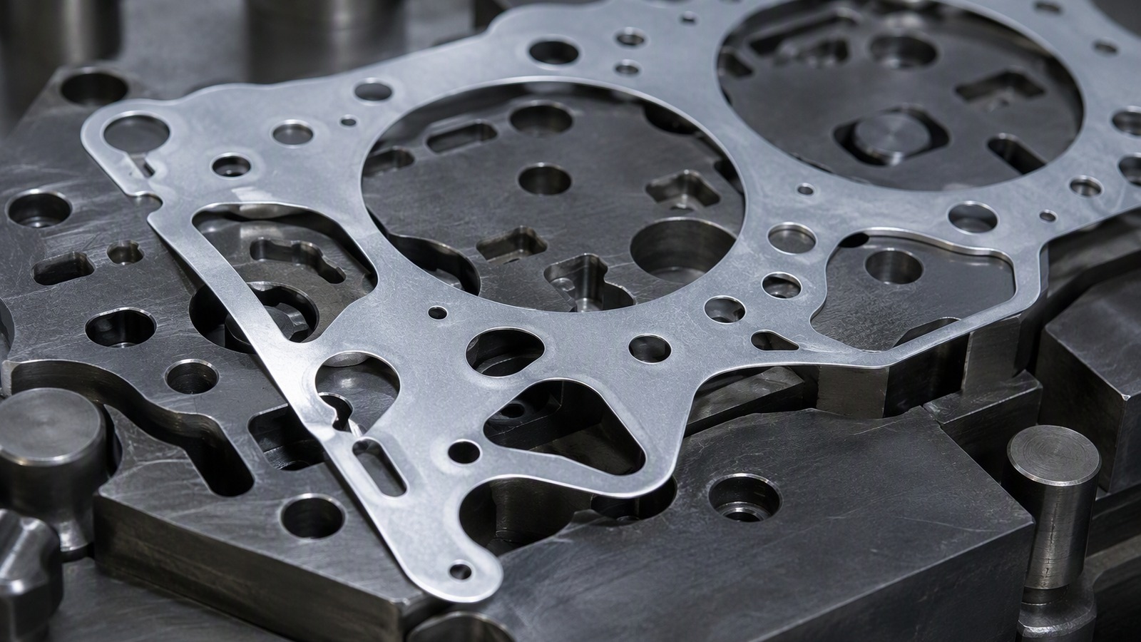
A gasket is judged at its edges. The face is protected by the facing, while the cut edge is bare metal exposed to the medium and the joint gap.
The edge is where metal is exposed, where burr sits and where a leak path opens between plies. Tool condition decides more than face finish.
Dive deeper
In service the face of the foil is covered, by an elastomer, graphite, a fibre facing or the mating flange itself. The cut edge is not covered. It faces the medium directly and, on a layered part, it also faces the gap between two plies. Burr or smeared metal on that edge becomes a capillary path and a stress raiser at once.
Punching and slitting leave different edges. A sharp punch with well-set clearance gives a clean shear and little roll-over. A worn punch tears the edge, leaving a burr on one side and a rounded lip on the other; the burr stops the plies seating flat.
Width consistency matters too: a strip that varies in width shifts the edge position from part to part, so a tang designed for a groove may sit partly outside it. Foil is held to a nominal gauge across a width range of 100 mm to 1500 mm, and the edge is what the tool meets first.
This is why a converter should ask for the edge condition and not only the gauge, and why the difference between aluminium foil and aluminium sheet is not only a matter of thickness class. Wrought sheet is supplied to be machined; thin strip is supplied to be cut, and the cut is part of the specification.
What happens at the joint under bolt load and after thermal cycling?
Under bolt load the joint closes, the facing conforms and the foil ply is pressed between two stiffer bodies. What happens next depends on how the stack relaxes.
The facing takes the seating stress and the foil spreads it. After thermal cycling the ply moves with the flanges while the facing creeps, so the stack must keep spring.
Dive deeper
As the bolts tighten the facing is squeezed first, being the softest element. Load then transfers into the metal ply, which is much stiffer, so a small further turn raises stress sharply inside the foil. A part designed without that in mind buckles its ply before the joint is tight.
Metal expands more than the soft facing and, in many assemblies, more than the flanges, so the ply grows against a joint that cannot follow. Cooling reverses it. Each cycle leaves a little permanent set in the facing and the bolt load falls, so the ply must keep pressing the facing into both faces.
A tang or folded locating tab records the history of a joint. If it is bright and polished, the part has been moving. If it is cracked at the bend, the ply has been cycled against a joint that was too stiff. Reading the tang after a strip-down tells more than reading the drawing. Published data on wrought products publishes general notes on wrought products that help, although joint behaviour is always specific.
The foil should therefore be chosen for the movement it will see, not the load it meets at assembly. A stiffer temper holds preload better but follows movement less well; a softer temper follows movement but relaxes sooner. That trade is the real subject of a gasket specification.
Why does the elastomer or graphite facing do the sealing while the foil does the separating?
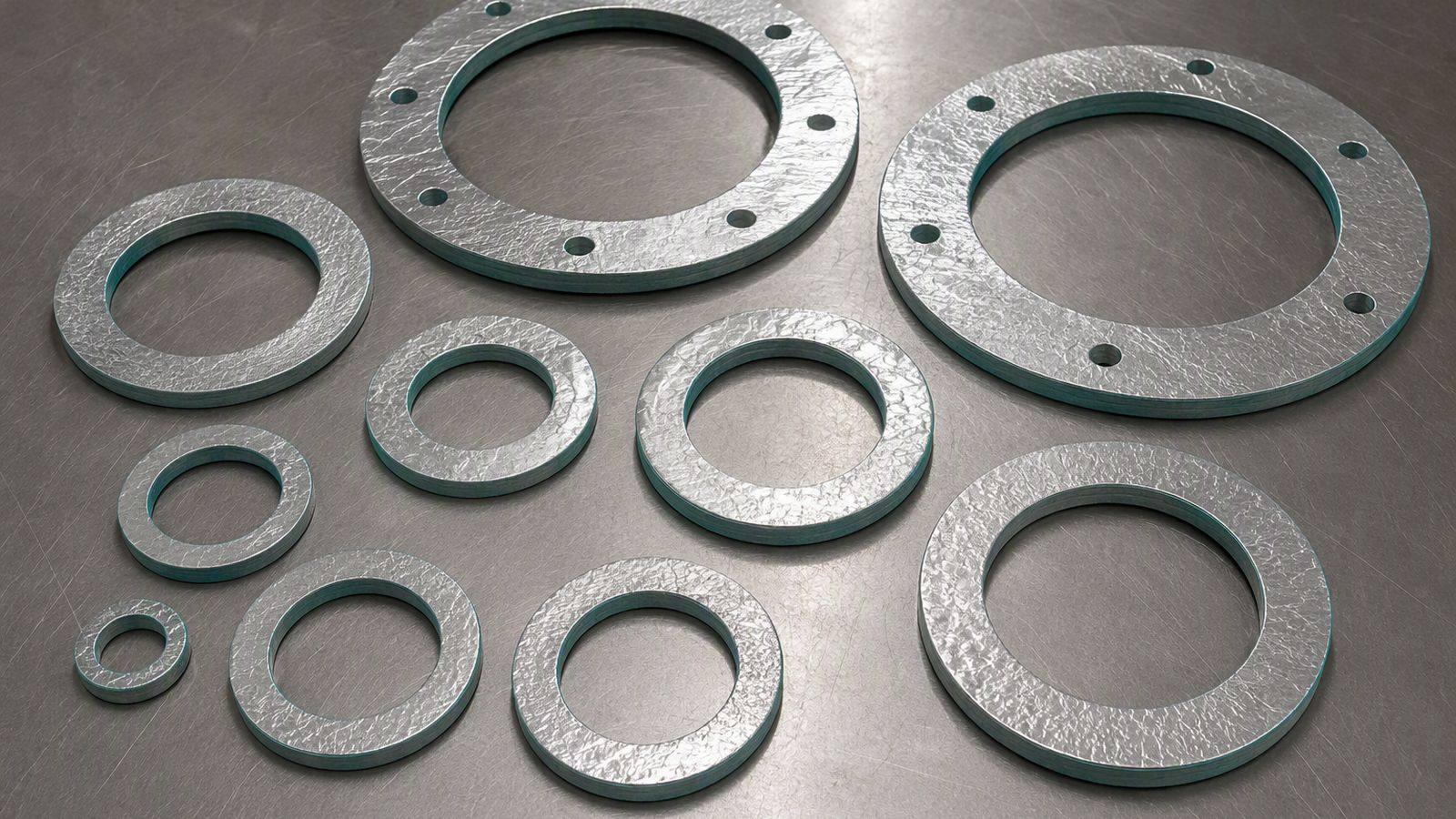
Sealing is a contact problem. Only a material that deforms into the surface texture of both faces can close a joint; a metal ply is too stiff.
The facing deforms and fills the micro-gaps; the foil cannot. The foil stops the medium travelling along the joint and holds the facing in place.
Dive deeper
A flange face is flat only in the drawing. In reality it carries tool marks, slight waviness and often a shallow spiral from machining. A seal has to fill those features. An elastomer does it by flowing under modest load; graphite does it by shearing between its own layers.
The foil therefore does the separating job. It blocks the path a medium would take between the plies, and prevents the soft facing from being extruded into the bore or out of the joint. In a spiral-wound body the strip also forms the chamber walls, so the filler cannot migrate.
Where the two duties are separated correctly, each material works inside its strength. The facing is never asked to carry the whole bolt load, and the foil is never asked to conform. Where they are confused, a designer may thin the facing to gain stiffness, and the joint weeps at the first thermal cycle because nothing is left to fill the surface.
This is also why facing thickness and foil gauge are chosen together. A thin facing over a stiff ply has nowhere to flow; a thick facing over a thin ply can be extruded. The pairing, not either layer alone, is the design decision, and it is the one an enquiry should describe in plain terms.
Why does a foil-only gasket leak where a layered one holds?
A foil-only gasket has no compliant element. It relies on two metal surfaces meeting closely enough to seal, a less forgiving mechanism.
Without a facing there is nothing to fill the surface texture, so the joint depends on flatness and load alone. It holds on a lapped face and weeps on a machined one.
Dive deeper
Without a facing the joint is metal on metal. The two surfaces touch at their high points only, and the space between those points forms a continuous channel from inside the joint to outside. Bolt load flattens some high points, but it cannot close the whole channel, and it cannot close any of it where the faces are not parallel.
A layered gasket closes the same joint because the soft layer fills the channel. The ply need not touch the flange; it only has to sit behind the facing and stop the medium finding a route along the joint. That is why a layered part holds where a plain foil ring would weep.
There are cases where a foil-only part is right: a joint between two well-lapped faces, a low-demand cover, a shim that also acts as a barrier. The mistake is to take a part that works there and put it on a machined flange in cyclic service.
The heat exchanger case shows the opposite error. There the foil is chosen for thermal duty and formed into fins, as described in the guide to fin stock, and nobody expects a fin to seal. A gasket foil is selected for closure and for its behaviour at a cut edge, a different brief even when the alloy is the same.
What must an enquiry contain?
An enquiry that names only an alloy and a thickness will produce a quotation that fits nothing. The part, the joint and the handling all change the answer.
State the alloy, temper, gauge, width, core, edge condition, quantity per size and destination port. Add the joint type, the facing material and how the part is formed.
Dive deeper
Start with the part: a flat ring, a spiral-wound strip, a folded tang, a shim or a facing laminate? Each has a different forming route, and the route decides the temper. A tang that is punched then bent needs more elongation than a ring that is only punched.
Then the joint: the two mating materials, the medium, whether service is static or cyclic, and how the part is located. The medium decides whether the foil needs a coating or a laminate; the location decides the tang geometry. State the facing material and thickness, since gauge is chosen against it.
Then the supply: alloy and temper in usual designations, gauge in millimetres, width in millimetres, core diameter, edge condition, quantity per size and port. A minimum order of 3 MT per size applies, and the ports used are Qingdao, Tianjin and Shanghai.
Finally, say what the part must not do. No leakage after thermal cycling, no cracking at the tang, no lifting of the facing, says more than a list of properties, because it names the failure to avoid. Industry notes on foil and similar bodies publish general notes that support that conversation; the specific answer still comes from the joint.
The foil separates, spreads load and holds shape; the facing seals. Specify both as one stack, and check the cut edge before the face.