Why Does Aluminium Foil Thin Out in a Deep Draw?
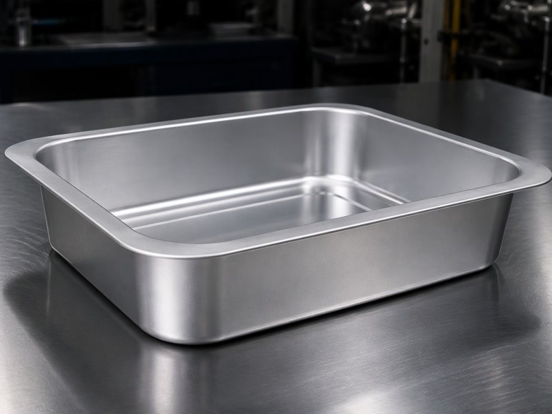
A drawn wall thins where the metal is stretched hardest, and the corner shows it first.
A container arrives, the corner looks pale and the wall measures light. Nothing on the drawing asked for that, and nobody admits to changing the tool.
A deep draw does not squeeze the wall thinner. It stretches the wall, and the wall is built from metal pulled in from the flange. Where that inflow runs short, the wall stretches to make up the difference, and the corner asks first.
That reframes the problem. The useful questions are no longer how much thinner the wall becomes, but where the metal came from, what had to give, and how much margin a buyer should hold.
What Does a Deep Draw Actually Do to the Metal?
The punch looks as though it presses a shape into a flat sheet. In a genuine draw it is doing something quite different, and that difference explains every thin wall.
The blankholder grips the flange, the punch pushes the centre through the die, and the wall is formed from metal drawn inward, then carried in tension over the die radius and the punch nose.
Dive deeper
Follow one element of metal through the stroke. It starts in the flange under the blankholder and is pulled radially inward toward the die opening. Because it travels toward a smaller circumference, its length around the axis must shrink, so it sits in circumferential compression while being pulled in radial tension. That is why a light blankholder lets the flange wrinkle and a heavy one starves the draw and thins the wall.
At the die radius the element bends, straightens and bends again as it turns up the wall, and each bend redistributes strain through the thickness. Once standing in the wall it is pulled, not pushed: the punch moves the bottom, the bottom pulls the wall, and the wall pulls the next ring of metal out of the flange. A draw is a tension chain, and every link must carry its share.
So punch force matters less than wall tension. A container that forms at one depth can tear at a greater depth in the same tool, because the wall must carry more load through a section that has already thinned. The metal has not been compressed; it has been stretched, and the stretch leaves a record a micrometer can find. The encyclopaedia entry on aluminium foil gives the terminology, though it treats thinning in general terms rather than as a setting problem.
Where Does the Wall Metal Come From?
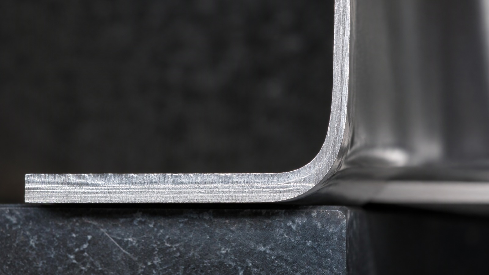
A wall is not created by the punch. It is borrowed from the flange, and the blank is the account it is drawn on.
Metal leaves the flange and becomes wall. How much flange is consumed sets how much wall can be built, so wall thickness is largely decided by the blank before the tool touches it.
Dive deeper
Treat the blank as a fixed budget. The finished part has to pay for a bottom, for the radii that turn the bottom into walls, for four walls, and for a trim allowance that will be cut away. Because volume does not change, available area and available thickness are two halves of one number: spread it over a larger developed area and the wall must be thinner.
During the stroke the flange behaves like a reservoir draining into the wall. Early on there is plenty of flange, punch load is modest, and the wall is fed rather than stretched. Later the flange narrows, the same load is carried by less metal, and the wall begins to strain. If the flange runs out before the punch bottoms, the rest of the stroke is pure stretching. The blankholder also takes a share: set it too firmly and the flange cannot flow, so the wall stretches instead of being fed.
Watch the outer edge on a trial and the mechanism becomes visible. The edge should draw inward steadily for a given punch speed and blankholder setting. Where it stops moving while the punch keeps descending, the wall has stopped being fed and started to give. The packaging and container foil range is offered in several gauges for exactly that reason.
Why Is the Wall Thinnest at the Corner and the Transition?
Thinning is rarely uniform. Two places show it first, and both are places where the metal has furthest to travel.
The corner of a rectangular part needs more wall length per unit of depth than a flat side, and it is fed from a narrower band of flange. The band above the bottom radius is bent and stretched at once.
Dive deeper
Take the corner first. In plan a corner is a curve, so the wall standing up from it is curved, and its developed length is longer than the flat wall beside it. The metal that feeds that arc must come from a corresponding arc of blank, and that arc is bounded on both sides by metal also trying to move. Flow is restrained from two directions at once, which leaves the corner short of metal.
Then the geometry. Over the die radius the metal bends and unbends; over the punch nose the same happens in the other direction. Between those zones the wall is a straight tension member, but at the bottom corner the two bending zones crowd together, and a narrow band just above the punch nose carries bending strain plus the tension that drags the rest of the wall along.
That band usually shows a bright polished stripe, and it fails first in a draw that is too deep for the material. Work also turns into heat at the corner, and friction drifts as the lubricant film thins under pressure, so a part that measured well at the start of a shift may measure differently at the end. Specify and measure the corner, not the flat side, and state the height at which it was read.
How Do Gauge, Temper and Alloy Shift the Thinning Pattern?
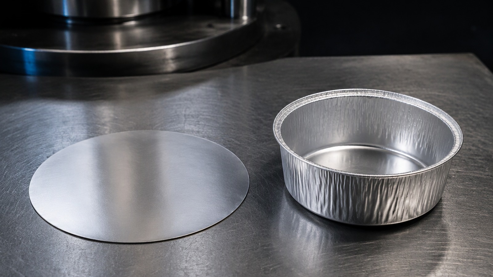
Three inputs move the pattern before a single tool dimension is chosen, and a buyer usually controls all three.
Gauge sets how much metal exists, alloy sets how far it stretches before strain localises, and temper sets how evenly that stretch is shared along the wall.
Dive deeper
Gauge works in two directions, which is why it is often misjudged. A heavier gauge puts more metal into the blank, so the wall can end heavier in absolute terms. It also raises punch load and stiffens the flange, so a blankholder setting that suited a lighter coil may now be too firm. A lighter gauge forms easily but leaves less reserve, and a drawn-out corner or a pinhole appears sooner. What a heavier gauge does not do is change the geometry of the strain, so the corner still asks for more than the flat side.
Alloy shifts the balance between strength and stretch. The near-pure grades, 1050, 1060, 1100 and 1235, elongate generously, so strain spreads along a longer length of wall instead of concentrating. The manganese and magnesium grades, 3003 and 3004, are stronger but elongate less, so the same corner concentrates strain over a shorter band. 8011 sits between the two families.
Temper then decides how that elongation is spent. Metal rolled hard has less uniform elongation left, so the wall reaches its limit sooner and over a shorter length; annealed metal has the most to give and the least stiffness once formed. None of it can be settled without the depth, which is why the comparison of which alloy suits which container only helps once depth and corner are known.
Why Does a Harder Temper Thin Differently From an Annealed One?
Two coils of the same alloy, one annealed and one work-hardened, can fail in completely different ways in the same tool.
An annealed wall spreads its strain over a long length and thins gradually. A harder temper concentrates strain in a short band, so the wall thins sharply and then stops cooperating.
Dive deeper
Aluminium work-hardens. A temper such as H14, H16 or H18 has already been rolled to a controlled amount of cold work, so part of its capacity to harden is spent before the press starts. As the draw strains the wall, the most heavily worked point hardens quickly, and because hardening raises the load needed for further strain, neighbouring metal takes more of the deformation instead.
That sounds helpful, and up to a point it is. The trouble is that the same mechanism shortens the window: the localised band reaches its limit while the rest of the wall is still comparatively unstretched. An annealed coil does the opposite, starting soft and hardening as it strains, so work keeps distributing and the corner is less of a step change. The visible result of the harder temper is a shorter, sharper zone rather than a long gradual loss.
What annealed metal does not offer is stiffness in the finished wall, and it wrinkles more readily in the flange. Half-hard tempers such as H22 and H24 are the compromise many container programmes settle on: enough hardening to hold a wall and survive handling, enough ductility to keep thinning spread out. Temper is not a free upgrade, because a harder one can move the weak point into a narrower band.
What Can the Tool Change, and Where Does the Material Decide?
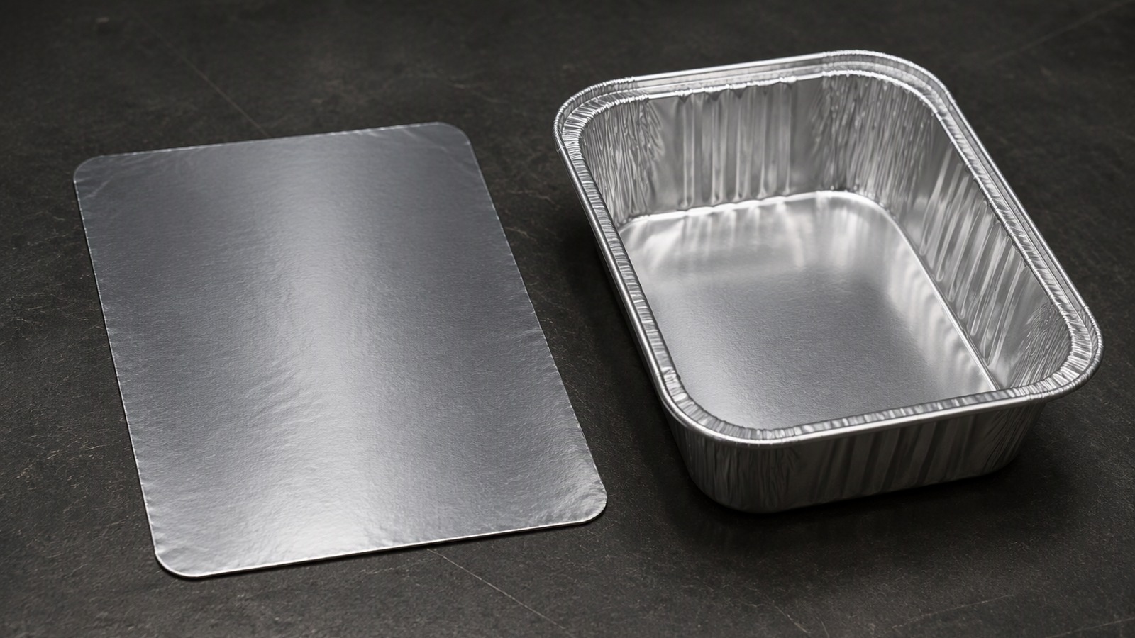
A tool can move strain around. It cannot add metal, and it cannot make a short blank feed a tall wall.
Radii, clearance, blankholder force, draw beads and lubrication all change how strain is distributed. Beyond a certain point the remaining limits belong to the coil, not the die.
Dive deeper
Radii do the most work. A generous die radius gives the flange a gentler path into the wall, lowers bending strain and lets more metal flow. A generous punch nose radius spreads the turn from bottom to wall over more surface. Both relieve the corner and both cost something: too generous a die radius lets the flange wrinkle, and too generous a punch nose steals plan area from the bottom.
Clearance decides whether the wall is simply drawn or also ironed. A tight clearance thins the wall deliberately and leaves a bright, uniform surface, at the price of load and tool wear. A loose clearance lets the wall thicken as it leaves the die, which sounds desirable until folds appear in the space. Between the two extremes sits the setting most tools run at, where the wall is drawn with light contact on the die face and no deliberate ironing.
Lubrication is the cheapest lever and the easiest to overdo. A good film lowers friction at the die radius, so the wall carries less tension and thins less. Too much lets the flange slide freely and trades a thin corner for a wrinkled one. Consistency matters more than quantity, since a film that varies across the strip leaves a wall that varies around the part.
Beyond these levers, tool design for heavy gauge foil comes down to stiffness rather than clever geometry.Why Does Blank Size Set the Limit Before the Tool Does?
Every argument about radii and lubrication can be settled by a blank that is either big enough or not.
The blank is the metal budget. Its area must cover the bottom, the radii, the walls and a trim allowance, and whatever is left is what the wall has to work with.
Dive deeper
Blank size is decided early and changed late at great cost, which is the wrong order. A blank is normally calculated from the developed area of the finished part plus an allowance for the flange the blankholder must grip. Get it right and there is enough metal to build the wall without stretching it hard. Get it small and no tool tuning recovers the shortfall: the wall strains further, and the corner strains furthest.
The shape matters as much as the area. A rectangular blank with generous corners gives the corner of the part more metal to draw from and reduces restraint from the adjacent sides. Blanking the corners back is a common way to feed a difficult corner without increasing blank area, at the cost of a blank that is less convenient to handle and a nesting pattern that needs more care.
An oversized blank is not a safe answer either: more flange means more restraint, higher punch load and more to trim away. Where the blank is already fixed by an existing tool, say so in the enquiry, because it tells the supplier that gauge, temper and alloy are the only variables left. Background from the European aluminium industry association helps frame the question; the answer for a specific part still comes from a trial.
How Do You Check a Thin Wall Yourself, and What Should an Enquiry State?
A thin corner is easy to suspect and surprisingly easy to measure, provided the reading is taken in the right place.
Measure at fixed clock positions and at mid-height, cut a section through the corner, and compare it with a flat side. Then state the minimum wall you can accept, not the nominal one.
Dive deeper
Start with positions, because an unpositioned measurement is not evidence. Mark four clock positions, read each between the bottom radius and the top edge, then read again just above the bottom radius. Most thin-wall complaints sit in one of those two places.
On a foil wall a point micrometer with a small anvil beats a flat anvil, which bridges the wall and reads its thickest point. Where a micrometer cannot reach, cut a strip, measure its area and weigh it. A bright stripe above the bottom radius says the same thing.
An enquiry works best with five facts: finished depth, plan dimensions including corner radii, the minimum wall that must survive and where, the alloy and temper you prefer, and the gauge you have in mind. Add whether a tool exists and what blank it uses, because 3003 aluminium foil for drawn containers behaves differently from a softer grade at the corner.
Margin is then a decision, not a hope. Specify the minimum, let the supplier propose the gauge that meets it, and ask for the corner to be reported separately; where depth is close to the limit, one trial in a softer option such as 1100 aluminium foil for formed parts settles it. Background from the American aluminium industry association and the European foil association frames the question.
Wall thinning is a budget, not an accident. Ask where the metal came from, measure the corner, and write the minimum wall into the enquiry.