Why does heavy gauge aluminium foil need a different tool?
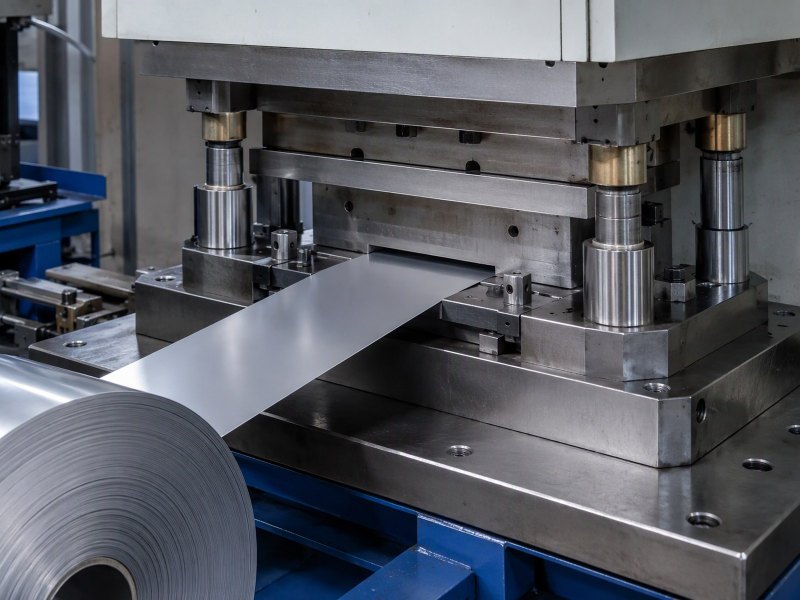
At the top of the foil range the strip stops draping and starts holding its own shape. This guide follows the tool consequences: clearance, burr side, springback, flatness, stacking, and how to read a part drawing before the tool is cut.
Why does heavy gauge aluminium foil need a different tool?
A drawing arrives for a part in 0.15 mm strip, and the tool that runs the plant's thin foil is quoted unchanged. The first samples come out bowed and burred.
Heavy gauge foil is cut with a tool set to its own gauge. Clearance, hold-down, edge and springback follow the strip, not the press.
Eight questions follow a heavy part from strip to assembly bench, and end with what an enquiry must state.
When does a heavy gauge foil part stop behaving like foil and start behaving like sheet?
The change is gradual on paper and abrupt in the tool. A foil at the bottom of the range simply follows the die.
At the top of the range the strip carries its own stiffness: it resists a tight corner, keeps a bend and bridges a gap. The tool has to control a part that is already arguing with it.
Dive deeper
A foil near the bottom of the range has almost no bending stiffness of its own: it lies on the face, follows whatever surface it is pressed against, and takes the shape of the die. As the gauge climbs towards the top of the range, the strip starts to carry load itself.
It resists being pushed into a tight corner, keeps a bend after the punch withdraws, and can bridge a small gap instead of draping into it. That is sheet behaviour arriving in a material still shipped as foil. The edge changes with it: on thin foil the cut edge is a line, on heavy strip it is a face with height, and shear, fracture and drag all show across that face.
Elastic energy changes too. Thin foil releases almost nothing when it is cut; heavy strip releases enough to move the part as the tool opens. A heavy part therefore cannot be treated as a thin part with more material in it. The dividing line is where the strip stops following the tool. The reference entry on aluminium foil covers how the metal is rolled; what a tool does with a given gauge is decided in the die design, and industrial and technical foil is where that range starts.
Why does a heavier gauge need a different clearance at the tool rather than more force?
The first instinct is to press harder. A heavy strip does not fail because the press is weak; it fails because the cut is aimed wrongly.
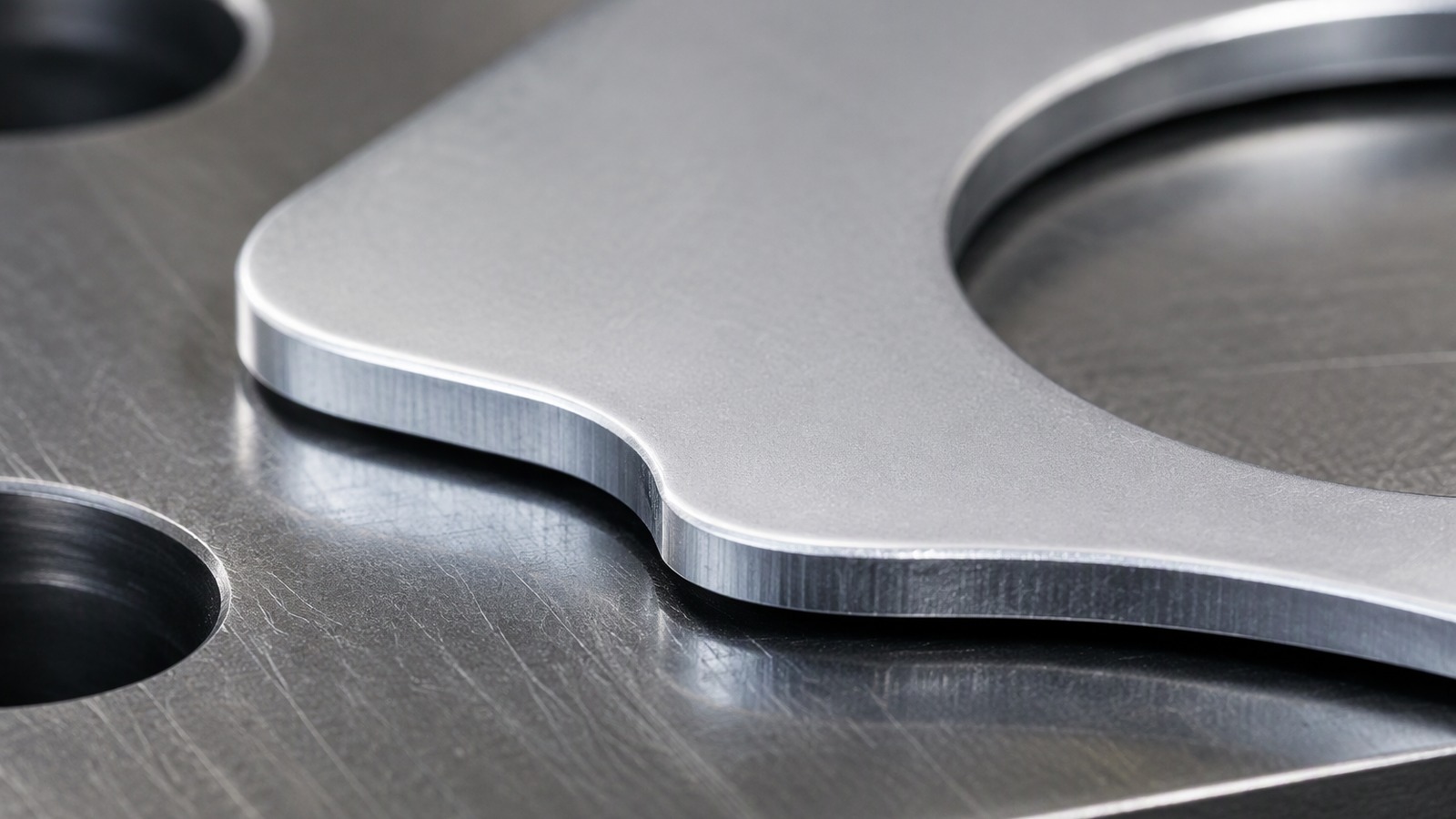
Clearance decides where shear ends and fracture begins. In heavy strip that band is a smaller share of a thicker section, so the tool is cut to the gauge; extra force only distorts the part.
Dive deeper
A cut edge is made in two stages. The punch pushes the strip into the material below and shears a band; then the remaining section tears. Clearance is the gap that decides where the shear stops and the tear begins. Set it for the gauge and the two meet cleanly. Set it for thinner material and the tear runs late, dragging metal down the edge.
In thin foil the gap is a large share of a very small thickness and the material is forgiving: it stretches, the tear wanders, nobody sees it. In heavy strip the same gap is a smaller share of a thicker section, so the geometry of the cut is decided by the tool rather than absorbed by the metal. More force does not correct that. It drives the punch into a section with nowhere to go, and the surplus appears as dishing and a part that will not sit flat.
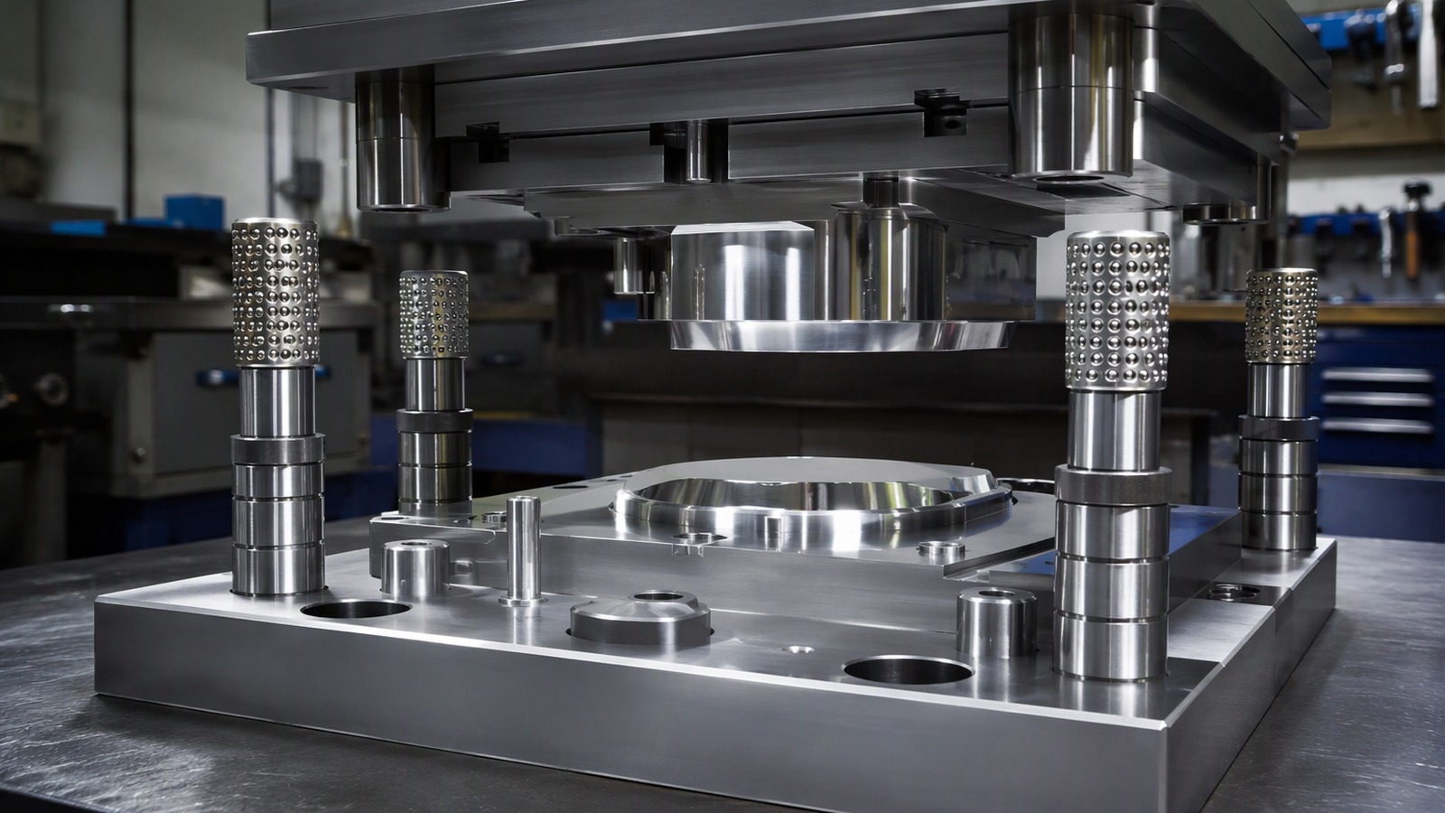
So the answer to a heavy part is a different tool, not a bigger press. Gap, punch and die corner condition, stripping pressure and the sequence of cuts are chosen together for the gauge, the temper and the alloy; 3004 aluminium foil at 0.12 mm in a hard temper behaves nothing like the same alloy annealed. Those values belong on the tool drawing, where the designer sets them against the section, not in a purchase order.
What causes a burr on a heavy foil part, and why does it matter at assembly?
A burr on a wrapper is a handling nuisance. On a heavy part it is a dimension: it lifts the part off its seat.
The burr marks where the fracture ran past the punch edge instead of meeting it. A dull edge, too much gap or a work-hardened strip all push it that way.
Dive deeper
A burr is not a defect of the material; it is the signature of where the fracture went. When the tear meets the punch edge, the edge is clean. When it runs past that line, a lip of metal is left hanging, and its size follows the gap, the condition of the punch and die, and the state of the strip.
Heavy strip makes that visible in a way thin foil never does. The lip has height and stiffness, so it survives handling and it survives the customer's line. It also has a side. A burr sits on one face of the part, and which face is a design decision: it should point away from the seating face, away from a sealing surface, and away from anything that slides across the part.
At assembly the consequences are physical. A burr on a seating face holds the part off its mating surface by its own height, so a joint designed to close on a face closes on a ring of metal instead; foil for industrial gaskets and seals shows how quickly that becomes a leak path. A burr on a sliding face scratches a coating. Tool wear moves the fracture line, so the burr grows through a run: the drawing names the acceptable condition, and maintenance follows the tool rather than a calendar.
Why does springback appear only above a certain gauge, and how does the part shape compensate?
Bend a thin foil and it stays where it is put. Bend a heavy strip and it opens again once the tool lets go.
Springback is the elastic core returning. In thin foil almost the whole section yields; in heavy strip a core stays elastic, so the shape has to absorb it.
Dive deeper
When a strip is bent, the outer fibres stretch and the inner ones compress; if the whole section yields, the bend stays. If a core in the middle stays elastic, that core behaves like a spring and pulls the bend open when the tool releases.
Thin foil has almost no elastic core to speak of, so the effect is small enough to ignore. Above a certain gauge the core is a real fraction of the section and the opening becomes a dimension the assembly has to live with. The temper decides how much: a hard temper stores more and returns more than an annealed one, and a tight radius relative to the thickness makes it worse.
Part shape is where the compensation lives. A formed feature can be overbent in the tool so that it relaxes to the drawn angle; a rib or a bead can stiffen a face that would otherwise bow; a flange can be made deeper so the assembly clamps it flat. All of that is design work done before the tool is cut, and all of it needs the free-state shape on the drawing. Published industry material on aluminium describes forming behaviour in general terms; the values for a given part belong in the tool drawing.
How does flatness change the way a heavy foil tool is designed?
A heavy part that is flat under the stripper can bow once released, because cutting lets stored stress out.
Flatness is a free-state property. The tool must hold the strip down through the cut and release it evenly, and the drawing must say whether flatness is judged free or clamped.
Dive deeper
Coil carries shape from the mill, a set along the length and a crossbow across the width, and a heavy strip carries more of it than a thin one because there is more section to hold the memory. Cutting then releases stored stress unevenly.
A blank that was flat under the stripper can bow the moment it is free, and the bow follows the layout: a part at the edge of the strip behaves differently from one in the middle, and a skeleton with narrow bridges lets the strip move between cuts, so two parts from one sheet can leave the tool with different shapes.
That changes the design. Hold-down and stripping pressure have to keep the strip on the face through the whole cut, the sequence has to release stress in a controlled order, and the layout has to keep parts far enough from the edge that the edge does not pull them out of shape. The drawing must say whether flatness is judged free or clamped, because a tool can meet one and miss the other. Foil producers' published material covers how coil shape is described; the allowance for a part belongs on the tool drawing, with the width the strip will run at, anywhere from 100 to 1500 mm.
Why does a heavier part need different handling and stacking?
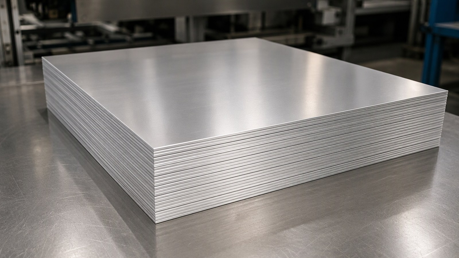
A foil part is light and rarely damaged by its own weight. A heavy blank is stiff, sharp-edged, and a stack behaves like thin plate.
Heavy parts do not drape. They rub, lock together and bend under their own weight, so stacking, interleaving and orientation belong in the process rather than in the packing note.
Dive deeper
A heavy blank is stiff, has a cut edge that will cut a glove, and weighs enough that a stack of them behaves like a stack of thin plate. The handling problem changes character at that point.
Parts that nest will lock together, and parts that do not nest will slide and rub, so the faces that matter, a seating face, a coated face, a face that will be seen, arrive scratched. Interleaving, orientation and stack height are process decisions, not packing details. Counting changes too: at this gauge the count per box is more reliably obtained by weight than by piece.
The tool contributes to this. Where the scrap skeleton is placed, how the parts leave the tool, whether they are pushed out flat or allowed to fall, and whether they arrive in a shingled line all decide how much handling the part sees before it is packed. A part that leaves the tool already oriented is cheaper to stack than one that has to be picked and turned. The sector's own guidance on handling and packing aluminium is a starting point; the actual packing is agreed with the mill, at a minimum of 3 MT per size, on pallets built for the weight.
How should a part drawing be read before a tool is cut?
A drawing that gives only the outline leaves the tool designer to invent the rest, and the invention is usually wrong.
Read for function first: which face seats, which face is seen, where the burr may sit, and whether flatness is judged free or clamped. Then cut the tool.
Dive deeper
The first read is functional: which face seats, which face is seen, which edge is handled, and where the part is fixed. Those answers set the burr side, the flatness condition and the edge requirement before any geometry is programmed.
The second read is geometric. Which radii are formed and which are cut, whether a bend line runs across the rolling direction or along it, how the tolerance stack closes against the mating part, and whether the finished part is measured free or in place. A heavy part usually needs a note on the burr side and a note on the flatness condition, because neither can be inferred from a profile, and neither can be left to the try-out.
The third read is about the strip. Part size against coil width decides the layout, the number of parts across, and how much scrap the tool will make; a part designed without that constraint can be impossible to run economically. Reading the drawing this way, before the tool is cut, is also how a buyer avoids a heavier gauge than the part needs: the difference between aluminium foil and aluminium sheet is a line worth holding in mind, because a part that only needs foil stiffness should not be specified as sheet.
What must an enquiry for heavy gauge foil state?
Most slow enquiries are not commercial. They are missing the part, the tool or the edge requirement.
State alloy and temper, thickness and width, the part drawing with the burr side marked, the flatness condition, the quantity per size and the handling.
Dive deeper
An enquiry that states the alloy, the temper, the thickness and the width gets a quotation. An enquiry that also states the part gets a tool that works. The difference is the drawing, the edge requirement and the flatness condition, and without them the first sample is a guess.
Say what the part does. State the alloy and temper, thickness inside the range from 0.005 to 0.20 mm, width inside 100 to 1500 mm, core diameter 76 or 152 mm, and the quantity per size against a minimum of 3 MT. Add the drawing with the burr side marked, the free-state flatness requirement, the faces that must not be marked, and how the parts will be stacked.
Then separate the two sets of numbers. Strip properties belong to the mill; clearance, hold-down, bend compensation and layout belong to the tool drawing, and the tool designer owns them. An enquiry that mixes the two invites a quotation against the wrong assumption. It is worth naming the lighter alternative where one exists too: a closure lid in 8021 aluminium foil at 0.06 mm is still a foil part, while a structural spacer at the top of the range is not. Loading is from Qingdao, Tianjin or Shanghai.
A heavy gauge part is designed at the tool, not the press. Read the drawing, set the clearance, and buy strip that matches both.